This article documents an ongoing debugging series. The vocoder sounds considerably better than it did at the start, but "sounds like a proper vocoder" hadn’t been achieved yet at the time of writing. I’ll update the conclusion once that changes.
1. The Plan
I’m building a small hardware vocoder on a generic Raspberry Pi Pico (RP2040) — as a hardware port of my browser-based software vocoder (Tone.js/Web Audio). Ingredients:
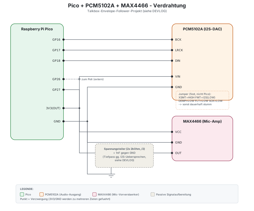
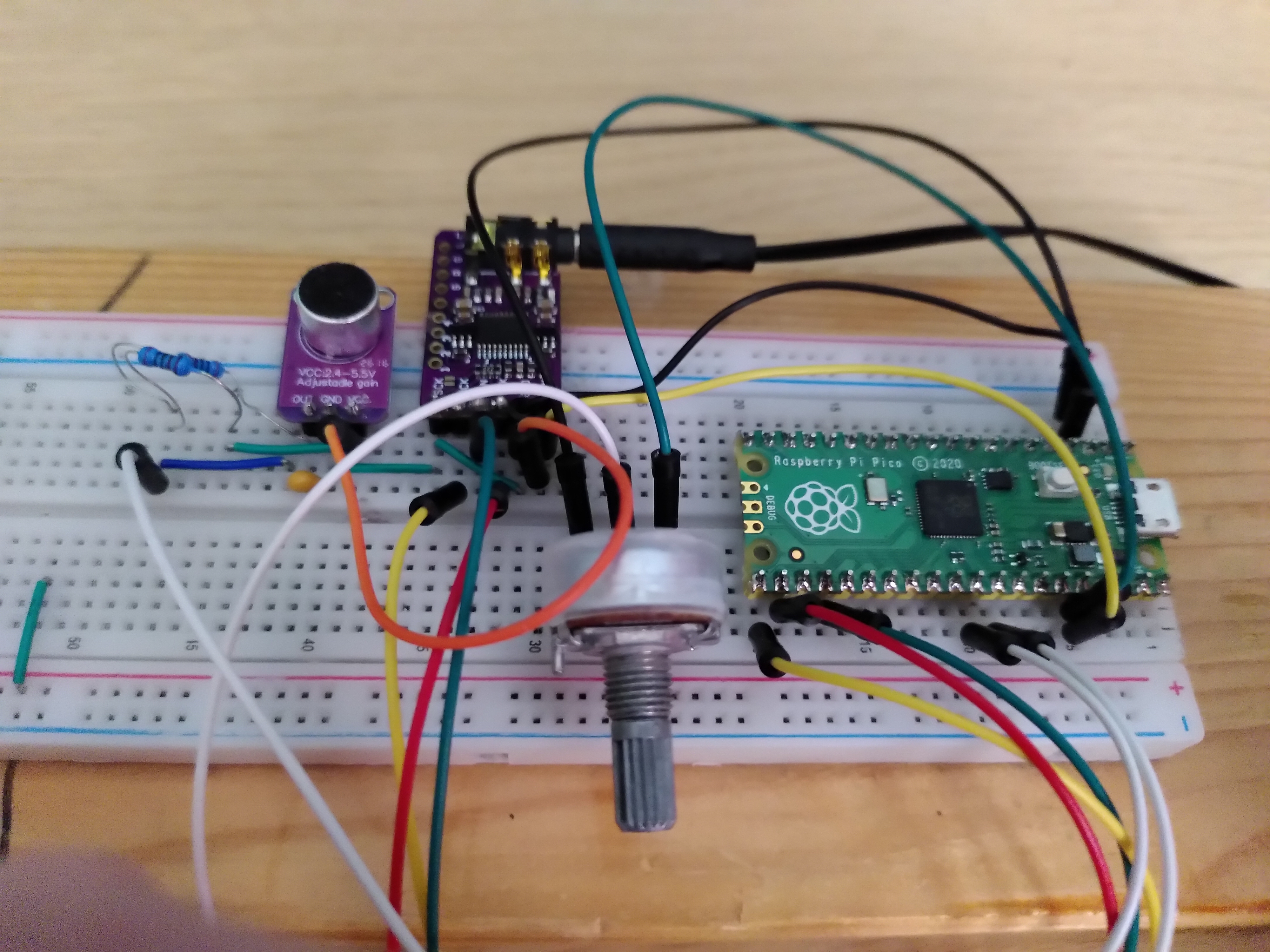
An electret microphone with a MAX4466 preamp as the modulator input
A PCM5102A I2S DAC for audio output
A potentiometer for carrier pitch
FreeRTOS, because I also wanted to use this project as practice with an RTOS on a microcontroller
The basic idea of a filter-bank vocoder is simple: split a modulator signal (the voice) into several frequency bands, measure only the loudness (envelope) per band, and use that to modulate the same frequency bands of an artificial carrier tone. The result sounds like a robot voice — if everything works together correctly. How much "working together correctly" actually entails wasn’t clear to me at the start.
2. Chapter 1: The Sine Wave That Wouldn’t Cooperate
The very first test setup (still on a PicoADK board, before I switched to generic hardware) was supposed to output nothing more than a 440Hz tone over I2S — no ADC, no FreeRTOS, just the raw audio signal path.
Two pitfalls right at the start:
The onboard DAC (PCM5100A) has an
XSMTpin (mute/unmute) that defaults to muted. Without explicitly setting it HIGH, the output stays silent — easy to mistake for a general I2S configuration error, since both failure modes look identical (silence).pico-extras(needed forpico_audio_i2s) has to be included via its own import file beforeproject()in CMake, not viaadd_subdirectory()afterwards. Otherwise the configuration runs through without errors, but the library simply never materializes as a build target — resulting in a confusingfatal errorfor a file that demonstrably exists.
After that: a clean tone. On to the actual project.
3. Chapter 2: From 1 Band to 12 — and the CPU Explodes
After a few intermediate steps (carrier oscillator, envelope follower for a single band), came the jump to a full 12-band filter bank with FreeRTOS. The first build ran — but the built-in timing measurement showed something sobering:
1
avg=51156us  budget=5804us   (at 44.1kHz, 256 samples/buffer)
8.6x too slow. The filter bank alone took almost 200µs per sample, while only 23µs were available.
3.1. The Dead End: -O3 Made Absolutely No Difference
Before I understood why it was so slow, there was an annoying
detour: I first suspected a broken build (-O0 instead of -O3).
But after repeated verification (embedding the build timestamp
directly in the diagnostic output, strings *.elf | grep for the
compiled diagnostic string), it was confirmed: the measurements
were identical, down to the microsecond, with confirmed -O0 and
confirmed -O3.
That only made sense once it clicked: the RP2040 has no FPU. Every
single float operation becomes a call into a precompiled software
library routine (__aeabi_fmul & co.) — and those routines don’t get
any faster through compiler optimization, because they’re finished,
precompiled functions, not inline instructions that -O3 could
improve.
Tip | If -O0 and -O3 produce exactly the same runtime on an
embedded target without an FPU, that’s itself a signal of
softfloat-dominated code — not (just) evidence of a broken build. |
3.2. The Fix: Q16.16 Fixed-Point
The solution was switching to Q16.16 fixed-point arithmetic (32-bit
signed integer, 16 integer/16 fractional bits) for everything running
in the sample hot path. Only the filter coefficient calculation
(sinf/cosf, once per band at startup) stayed in float — there,
readability matters more than speed.
1
2
3
4
5
6
using q16 = int32_t;
constexpr int kQ16Frac = 16;

inline q16 q16_mul(q16 a, q16 b) {
    return (q16)(((int64_t)a * (int64_t)b) >> kQ16Frac);
}
Result: 3.56x faster — noticeable, but not enough yet. The M0+ core
has a single-cycle 32×32→32-bit multiply, but no native 64-bit
multiply, which our q16_mul() needs — the compiler synthesizes that
across several instructions.
3.3. Three Free Optimizations
Instead of tweaking the architecture further, three purely algebraic transformations helped, with zero loss of precision:
For our bandpass design (RBJ cookbook formula, constant 0dB peak gain), the coefficient
b1is structurally always exactly 0 — the multiplicationb1*xwas pure wasted compute.Likewise,
b2 == -b0, exactly —b2*xcan be obtained from theb0*xalready computed fory, just by flipping the sign, instead of computing a second multiplication.The envelope smoothing
coeff*envelope + (1-coeff)rectifiedis algebraically identical toenvelope + (1-coeff)(rectified-envelope)— one multiplication instead of two.
Combined with lowering the sample rate to 22.05kHz (our highest band frequency sits well below that, no loss of information), this got me under budget — from 8.6x too slow to a comfortable margin.
4. Chapter 3: FreeRTOS Teaches Me Something About Scheduling
4.1. One ADC, Two Consumers
The potentiometer and the microphone hang off the same RP2040 ADC (just one hardware mux with a single "currently selected channel" state). Two FreeRTOS tasks switching independently would rip the channel out from under each other mid sample-loop — with no error message, only visible as corrupted audio. Solution: only one task ever touches the ADC; the raw value travels to a second task, which handles the smoothing, via a queue.
4.2. The Potentiometer That Was Presumed Dead
Once everything else was working, the potentiometer simply didn’t
respond to being turned at all — carrierHz stubbornly stayed at its
startup value. Diagnostic values showed: the raw pot reading came
through cleanly, but it never reached the task responsible for
smoothing it.
The cause was a textbook example of preemptive scheduling: the audio
task had not a single genuine FreeRTOS blocking point anywhere in
its loop — take_audio_buffer() from pico_audio_i2s is written for
bare metal, not FreeRTOS-aware blocking, presumably pure busy-spinning.
Under preemptive scheduling, the scheduler only switches to a
lower-priority task when the currently running task genuinely
blocks — not just when it "has nothing to do right now." Without a
real blocking point in the audio task, the pot task never got any CPU
time at all, and its own vTaskDelay() never elapsed.
1
2
3
4
5
6
// Forces the audio task into a real, brief blocking point where the
// scheduler CAN switch to the pot task.
if (++yieldCounter >= 2) {
    yieldCounter = 0;
    vTaskDelay(1);
}
One line of code, but one of the most instructive hours of the entire project.
5. Chapter 4: "Sounds Like a Modulated Hum"
With working timing and a working pot, came the most sobering part: the vocoder produced a tone that got louder/quieter with speech — but no recognizable speech. What followed was a long series of individual tests, tried and discarded one after another:
Narrowed the band range from 100–8000Hz to 200–4000Hz (telephone- band principle) → barely any difference
Lowered Q from 4 to 2 (assumption: narrower = more sluggish) → wrong assumption
Coupled attack/release per band to frequency → improvement, but not the breakthrough
The actual progress only came once I stopped testing my own guesses and instead used my working software vocoder as a reference. Two concrete assumptions were directly disproven: Q=2 was wrong (the reference uses Q=5, higher than even my original value), and the band narrowing went in the wrong direction (the reference uses 90–6000Hz, closer to the original range).
5.1. A Sawtooth Doesn’t Reach the Formants
A sawtooth carrier has a 1/n harmonic rolloff. At a fundamental frequency of, say, 200Hz, the harmonic at 2kHz is already the 10th overtone — with strongly reduced energy. But that’s exactly where (800Hz–3kHz) the formants F2/F3 live, which distinguish vowels from one another. The analysis correctly detected different energy per band, but the carrier had nothing left to shape there. Result: loudness modulates, timbre stays the same — a "modulated hum."
Fix: a narrow pulse train (20% duty cycle) instead of a sawtooth — historically the standard carrier for vocoders, for exactly this reason. A narrow pulse has a much more even, broadband harmonic spectrum.
5.2. A Real Compressor Instead of Hard Clipping
My reference implementation uses a proper compressor (threshold, ratio, attack/release) instead of a hard clip on the summed output. A hard clip cuts off signal peaks abruptly (harsh/metallic), a compressor squeezes them down gently and preserves more fine detail. In fixed-point, this could be built using the envelope-following infrastructure I already had — just one division per sample for the dynamically changing compression gain, everything else precomputed.
5.3. Voiced/Unvoiced Detection: Two Attempts
A static noise ratio mixed into the carrier (a fixed percentage of noise blended with the pulse train) can’t serve vowels and consonants well at the same time — vowels need a clean tonal carrier, consonants need noise energy. My first attempt (zero-crossing rate) never had properly calibrated thresholds. The reference implementation showed a proven alternative: split the signal around 1.5kHz into a low and high component, track a smoothed level for each, and use the difference as the decision.
The first calibrated threshold had a reasoning error: I had assumed the high-frequency component had to exceed the low-frequency one in absolute terms. Real measurements showed otherwise: sibilants only reach ~20–26% of the low-band level, never 100% — sibilants are inherently quieter than vowels, acoustically. The threshold needed to be defined as a ratio, not a comparison between two absolute quantities.
6. Chapter 5: The Second Core
An externally shared reference vocoder on a Teensy 3.6 pointed me toward what should have been the obvious idea all along: the RP2040 has two cores, and I was only using one.
The key design decision here: Core1 runs entirely outside of
FreeRTOS, as a raw pico_multicore loop — no second RTOS instance
introducing a whole new class of concurrency risk, after everything
I’d already learned from ADC sharing and priority starvation. Just two
handshake signals per buffer (not per sample):
1
2
3
4
// Core0: preparation (ADC read, carrier build) -> fill shared arrays
multicore_fifo_push_blocking(1);   // start Core1
// Core0 computes its own half SIMULTANEOUSLY
multicore_fifo_pop_blocking();     // wait for Core1's done signal
Result: band-processing time dropped to a bit more than half — while running 12 bands instead of 10 at the same time. Plenty of headroom for future experiments.
When the sound still wasn’t convincing despite everything, the
two-core synchronization itself became a suspect — a compiler could
in theory reorder writes to ordinary (non-volatile) global arrays
around the FIFO handshake. A diagnostic switch (kUseSecondCore)
that pulls Core1 entirely out of the signal path for testing showed:
identical result with and without the second core. Suspicion cleared
— but at least conclusively ruled out rather than merely assumed.
7. Chapter 6: Where Does the Energy Go?
The most revealing diagnostic step so far: instead of only exposing aggregate values (sum, overall envelope), I printed the envelope of each of the 12 bands individually.
1
bands[0..11] = 40 41 22 16 12 8 5 3 0 1 0 1
A smooth, monotonically decaying curve from band 0 (90Hz) down to about band 7 (~1.5kHz), then essentially nothing — regardless of whether "iii" or "uuu" was spoken. That doesn’t look like a software bug (which would tend to look jumpy/irregular), but like a genuine low-pass characteristic somewhere in the analog signal path.
7.1. The Voltage Divider That Shifted the Operating Point
After the mic trimmer was already at its (presumed) limit and the signal was still clipping, I added an external voltage divider for extra attenuation. That introduced a new problem: the divider doesn’t just attenuate the AC amplitude, it also shifts the DC operating point along with it — but my code still assumed the original ADC midpoint.
Instead of recalculating the new operating point by hand (which I did at first, and which would have been wrong again the next time a component changed), the code now continuously tracks the DC component itself, via a very slow low-pass filter:
1
2
3
4
5
// ~300ms time constant - well below the lowest band frequency
// (90Hz), continuously tracks the DC bias regardless of the
// exact analog wiring.
g_micDcState += q16_mul(g_micDcUpdateRate, rawQ16 - g_micDcState);
return rawQ16 - g_micDcState;
That was the third fix in a row for the same underlying issue — time to solve the problem structurally instead of patching it point by point.
7.2. Gain Costs Bandwidth
The MAX4466 datasheet supplies a concrete number for the remaining low-pass character: a gain-bandwidth product of 600kHz, with the trimmer’s gain range spanning 25×–125×. At 125x gain, only about 4.8kHz of usable bandwidth remains — a fundamental op-amp trade-off, not a misconfiguration. A comparison test without the voltage divider confirmed it: the band pattern widened noticeably (activity reaching band 7–8 instead of band 3), but not completely — both effects (divider loading and the gain-bandwidth trade-off) appear to be stacking on top of each other.
8. Where Things Stand
What’s now working reliably and has been individually verified:
CPU budget: from 8.6x too slow to a ~39% margin
FreeRTOS priority-starvation bug fixed
Compressor instead of hard clipping
Two-core split of the filter bank (timing AND correctness verified)
Voiced/unvoiced detection cleanly separates vowels from sibilants
Noise gate with hysteresis (no more chattering)
Mic operating point self-calibrating
Still open: the signal path audibly loses energy in the upper frequency bands — likely a combination of the gain-bandwidth trade-off at the mic preamp and the extra load from the voltage divider. The next step is to lower the gain at the analog front end itself (instead of keeping it as high as possible on the trimmer and only compensating for the resulting overdrive afterward with a voltage divider) — and then see whether the upper bands finally come to life.
9. Lessons That Apply Beyond This Project
On chips without an FPU, identical
-O0/-O3runtimes are a finding in themselves, not just a hint of a broken build.Preemptive scheduling only switches on genuine blocking, not on idleness. A task that never blocks starves every lower-priority task — regardless of tick rate.
A working reference system is worth more than ten of your own theories. The single biggest jump in progress on this project didn’t come from clever debugging, but from giving up on guessing and instead copying a known-working implementation step by step.
A voltage divider shifts not just the amplitude, but the operating point too. And: higher gain on an op-amp fundamentally costs bandwidth — that’s physics, not a bug.
Measure before you guess — even when it’s tedious. Nearly every major breakthrough in this project came from a new diagnostic number, not a new idea.
To be continued, once the vocoder actually sounds like a vocoder.